bTicino MyHome Configuration
This chapter describes how to setup a bTicino MyHome domotics system.
Introduction
Communication with a bTicino MyHome system requires an OpenWebNet gateway. This is a component that acts as a gateway between your ip network, and the local bus. Examples of gateways are
- bTicino F452
- bTicino F454
- bTicino MH200
Some years ago, bTicino was bought by Legrand. The same components are available under the Legrand brand, but with different part number. Please check their respective websites :
Here, we will discuss the setup of the MyHome system using a MH200 component.
Configuring the MH200 using the TiMH200 software
Before you can send commands from your IP network, the MH200 component needs to be configured. The first configuration will have to be done using a RS232 connector (usb programmation cable 3559, see My home usb programming cable for pc 3559 for a picture).
- the bTicino tools need to be run from an ip address outside the range of enabled ip addresses
- any other communication needs to be run from an ip address within the range of enabled ip addresses
MyURemote makes use of the second option, so we need to setup the MH200 to accept commands from our MyURemote app.
Download and install
- Download the TiMH200 software and manual, and install the software
Configuration
- Start the software. A dialog box will show up
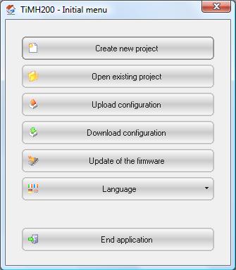
- Click Create new project.
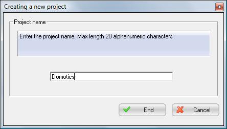
- Enter a name for your project
- Click End. The project window will open.
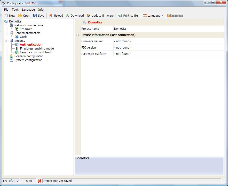
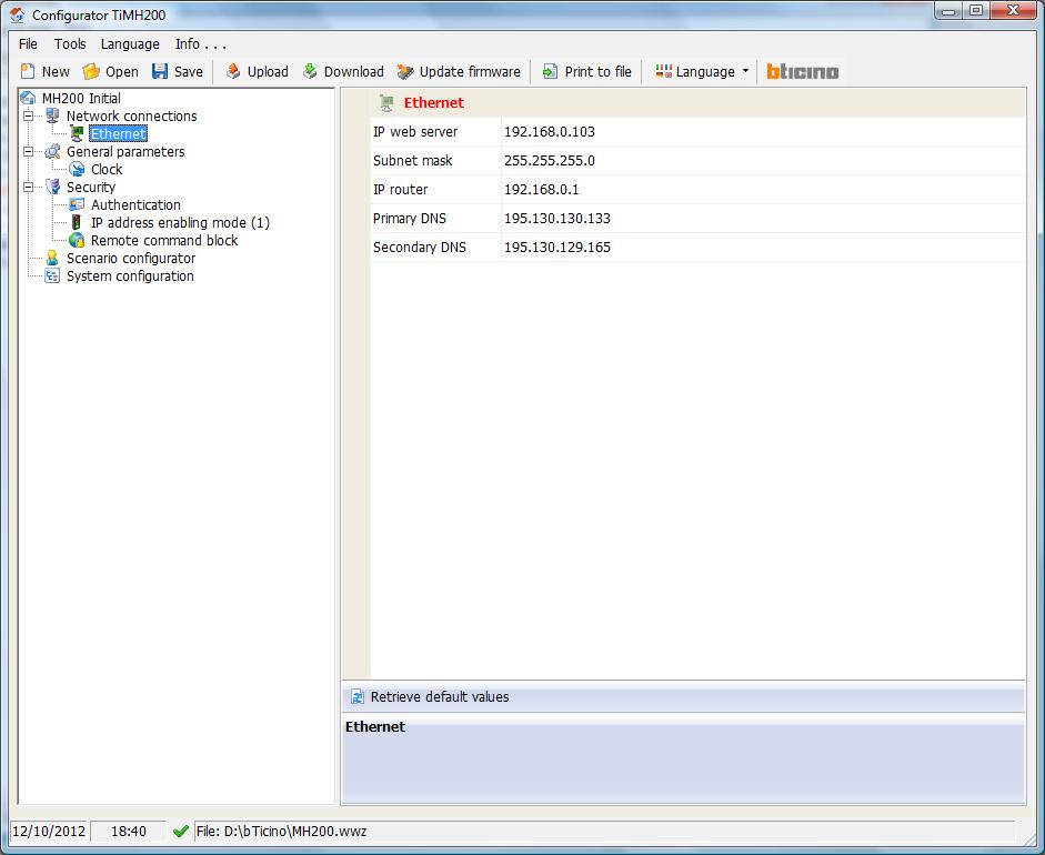
- In the left menu, select Ethernet
- In the right panel, you need to enter the network data of the MH200 component.
- IP web server : ip address of the MH200 component
- Subnet mask
- IP router : the ip address of your router or internet gateway
- Primary DNS
- Secondary DNS
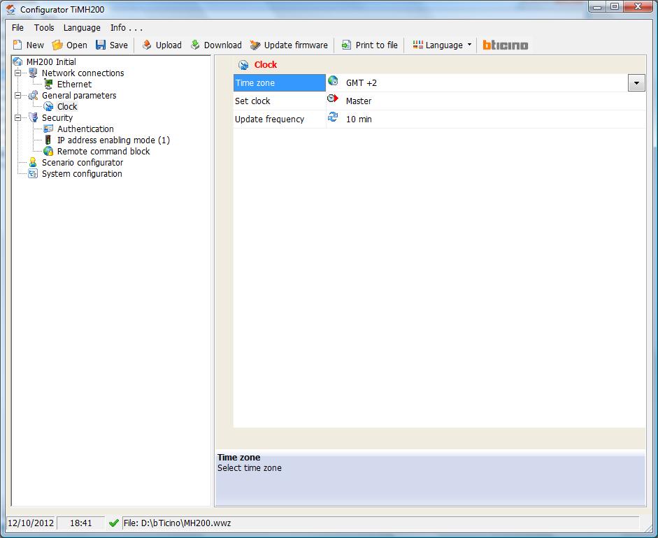
- Select the Clock menu entry in the left panel to select the right time zone
- Select the Authentication menu entry in the left panel, and define a new password that you will need to use when connecting via Ethernet. The password is shown in plain text, so no screenshot !
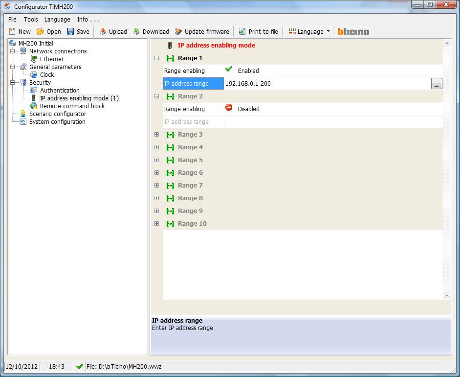
- Select IP address enabling mode in the left panel
- You need to define a range of ip addresses that are allowed to connect to the MH200 without a password. This range needs to include all devices (smartphones, tables, PC's) from which you want to run MyURemote. However, keep a (small) range of ip addresses for which you do need a password. You will need to select an ip addres from this disabled range if you want to use the TiMH200 software on the network.
- Click the Download button to send the configuration to the MH200 device.
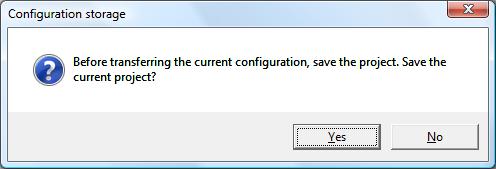
- Click Yes to save the project before sending it to the MH200 device. Select a location and a file name.
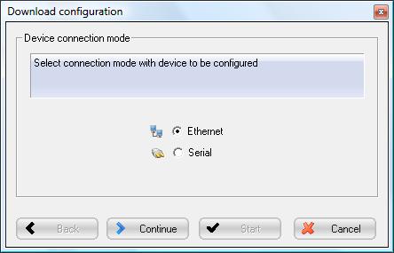
- Select a connection mode and click Continue
- The first time, you will have use a Serial connection, as the device won't have an ip address.
- From then on, you can select Ethernet. Be sure to do this from a PC with an ip address outside the range of enabled ip addresses, see above. Temporarily change the ip address, if necessary.
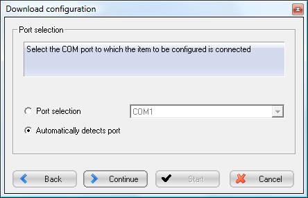
- We have chosen a Serial connection, we now have to select the port
- Leave the seletion to Autodetect, and click Continue
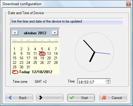
- Select date and time, and click Start
- When the configuration is sent to the MH200 device, you will receive a confirmation. Click OK to close the dialog box.
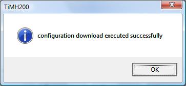
- You get a final feedback message that the configuration was successfully downloaded. Click End to close this dialog box, and to return to the project window.

Creating Scenarios
You can use the TiMH200 software to create scenarios for your MyHome system. This has nothing to do with MyURemote, but a short how to is presented here.
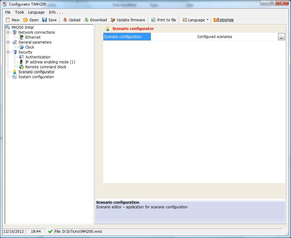
- Click the Scenarios entry in the left menu. In the right panel, a single line is shown. On the far right of this line, a button becomes visible when you hover your mouse over this line. Click this button to open the Scenario Editor.
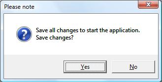
- Click Yes to save changes, if asked to
- The Scenario Editor is loaded.
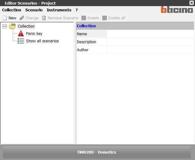
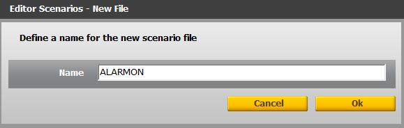
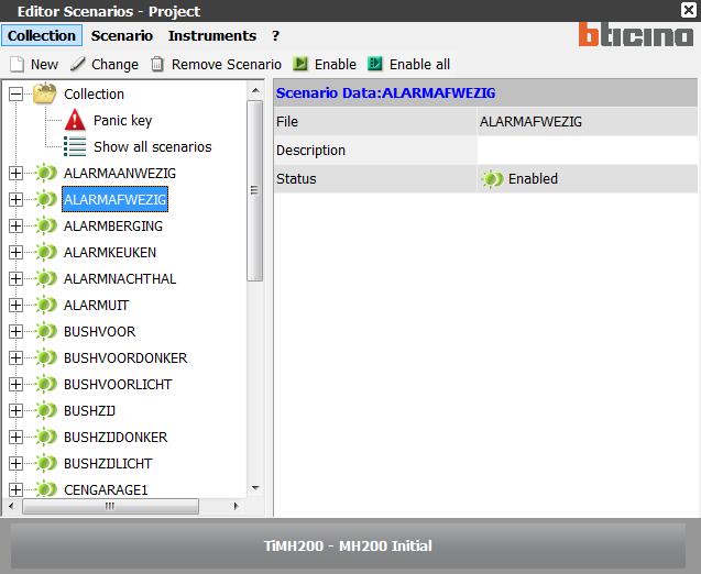
- Click New to create a new scenario. Enter a name for your scenario.
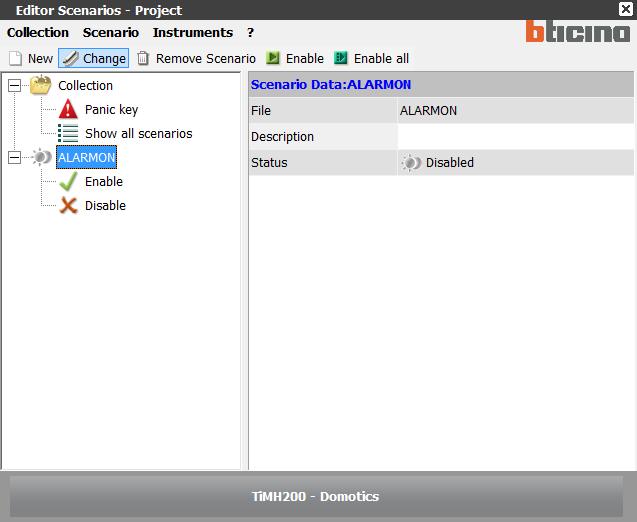
- The scenario is now added to the left panel of the Scenario Editor. Select it, and click Change in the menu.
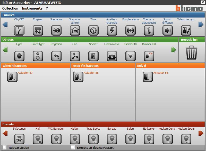
- An example of a scenario is shown here. You can select from different families of components. When a family is selected, the available objects are shown in the second row. The tool is too versatile to document in a couple of screenshots. For more information, see the TiMH200 manual.
- When you have finished creating and editing scenarios, click Collection and select Exit in the menu, to exit the Scenario Editor
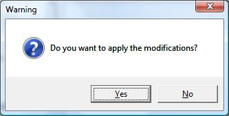
- Click Yes to apply the modifications
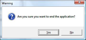
- Click Yes to end the Scenario Editor. You now return to the Project window.
- Click the Download button to send the configuration to the MH200 device.
- Click Yes to save the project before sending it to the MH200 device. Select a location and a file name.
- Select a connection mode and click Continue. Supposing that the initial configuration has already been sent to the MH200 device, we can select Ethernet.
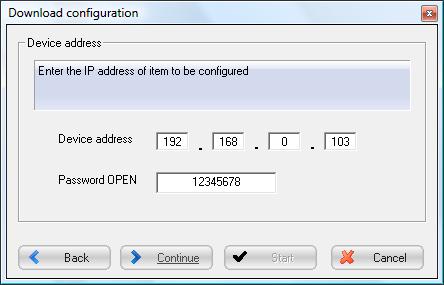
- Enter the ip address of the MH200 device, and the password you have previously setup. Click Continue
- Enter date and time, and click Start
- When the configuration is sent to the MH200 device, you will receive a confirmation. Click OK to close the dialog box.
- You get a final feedback message that the configuration was successfully downloaded. Click End to close this dialog box, and to return to the project window.
OpenWebNet protocol
The protocol is documented on Wikipedia.
To communicate with an OpenWebNet device, you send commands over a socket. A command to change the status of a component, looks like
*WHO*WHAT*WHERE##
- WHO specifies the type of component, e.g. 1 for Lights, 2 for Shutters, …
- WHAT specifies the target status, e.g. 0 for Light Off, 1 for Light On, and other values for shutters and other component types
- WHERE is the address of the light or the shutter on the local bus. The address can vary from 0 to 99.
Some examples
| Put light with address 31 on | *1*1*31## |
| Put light with address 31 off | *1*0*31## |
| Move shutter with address 81 up | *2*1*81## |
| Move shutter with address 81 down | *2*2*81## |
| Stop moving shutter with address 81 | *2*0*81## |
You can test this, from a PC with an ip address within the range of enabled ip addresses (see above). On linux
echo "*1*1*31##" | netcat <ip address> 20000
with <ip address> the ip address of the OpenWebNet gateway.
Or, if you have telnet on your PC
telnet 192.168.0.103 20000
Trying 192.168.0.103...
Connected to 192.168.0.103.
Escape character is '^]'.
*#*1##
Now enter the command
*1*1*31##
This should put on the light on address 31. The full communication is repeated here.
Trying 192.168.0.103...
Connected to 192.168.0.103.
Escape character is '^]'.
*#*1##*1*1*31##
*#*1##Connection closed by foreign host.
See Sample 6